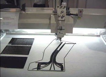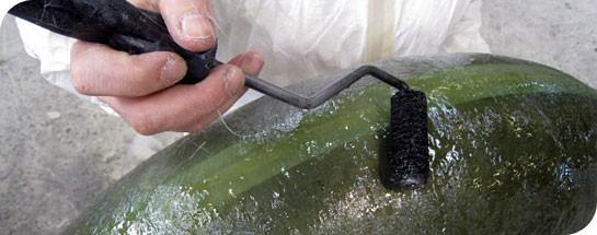
Hand layup is an open contact molding in one-sided molds are the lowest-cost and most common processes for making fiberglass composite products and is the most common method of producing composites parts in the U.S. aircraft industry.
In a typical open mold application, the mold is first waxed and sprayed with gel coat. It then may be cured in a heated oven at about 120∫ F. In the spray-up process, after the gel coat cures, catalyzed resin (usually polyester or vinyl ester at 500 cps to 1000 cps viscosity) is sprayed into the mold, along with chopped fiberglass. A chopper gun chops roving (usually E-glass) directly into the resin spray, so that all materials are simultaneously applied to the mold. Using low-styrene and suppressed-styrene resins, fillers and high-volume/low-pressure spray guns or pressure-fed resin roller applicators helps reduce emissions of volatile organic compounds.
In hand lay-up processing, fiberglass (typically E-glass) continuous strand mat and/or other fabrics such as woven roving are manually placed in the mold. Each ply is sprayed with Catalyzed resin (1000 to 1500 cps) and the resin is worked into the fiber with brushes and rollers to wet-out and compact the laminate.
Fiber content can be increased by up to 50 percent by curing the part in a vacuum bag, using 2 psi to 14 psi vacuum pressure and cure temperatures under 350∫ F. Vacuum-assisted resin transfer molding (VARTM) and infusion molding systems are gaining favor with open-mold processors wanting to cut volatile organic compounds emissions. The applied vacuum compacts the preform and helps the resin to penetrate and wet-out the fiber preform. Fiber content up to 70 percent has been reported.
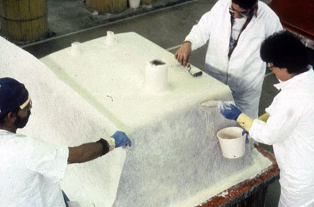
MATERIALS OPTIONS:
Resins: Any, e.g. epoxy, polyester, vinylester, phenolic.
Fibers: Any. woven or stitched into a fabric form.
Cores: Any
TYPICAL APPLICATIONS:
Most of aircraft composite parts, boat hulls and decks, RV components, truck cabs and fenders, wind-turbine blades etc.
SPRAY LAYUP:
Spray-up is an open-molding composites fabrication process where resin and reinforcements are sprayed onto a mold. The resin and glass may be applied separately or simultaneously "chopped" in a combined stream from a chopper gun. Workers roll out the spray-up to compact the laminate. Wood, foam or other core material may then be added, and a secondary spray-up layer imbeds the core between the laminates (sandwich construction). The part is then cured, cooled and removed from the reusable mold.
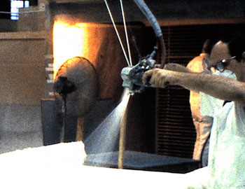
Spray layup has very little application in aerospace. This technology produces low specific strength structures which usually do not belong on the end product. Spray layup is being used to join back-up structures to composite face sheets on composite tools. Spray layup is also in limited use for obtaining fiberglass splash from transfer tools.
FILAMENT WINDING:
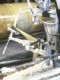
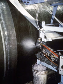
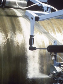
This process is primarily used for hollow, generally circular or oval sectioned components, such as pipes and tanks. Fibre tows are passed through a resin bath before being wound onto a mandrel in a variety of orientations, controlled by the fibre feeding mechanism, and rate of rotation of the mandrel.
While filament winding machine design varies with part geometry, the basic filament winding process concept is described in the following schematic.
The fibres are impregnated with resin (by immersion, or by passing over a resin-wetted drum, or by injection into the die) before being led to a feed eye where a controlled band-width is set prior to positioning on the mandrel.
Fiber tension is critical to the operation of a filament winding machine. The fibers are supplied on creels and it is normal to have fiber tensioners (closed-loop controlled servo-driven "dancers") in the feed line. The tension required is dependent on the type of fibre, the part diameter and the winding pattern selected. The tension directly affects both fibre volume fraction and void content and, in turn, influences the strength and stiffness of the composite part.
Once the fiber package is positioned the resin is taken to full cure, often by heating in an oven. The final stage is mandrel removal to leave the desired hollow component. This may be achieved by hydraulic rams for extracting steel mandrels. For more complex structures, the mandrel may be a low melting point materials (eg metal alloy) or a water soluble salt (leachable plaster) which can be washed out or a collapsible rubber or a non re-useable foam. In some cases, where a liner is required for minimal gas permeability the liner may also function as the mandrel and hence not need to be removed.
Filament winding has been combined with other fiber application methods such as hand layup, pultrusion, and braiding. Classic filament winding involves a spindle with a carriage or carriages to apply hoop and helical fibers. Compaction is through fiber tension. Resin content is now primarily metered. The machines are generally all computer controlled with up to six axes independently monitored. The additional axis comes into play at the fiber turn-arounds. The extra head axis allows for better placement of the band, and more uniform band width.
MATERIALS OPTIONS:
Resins: Any, e.g. epoxy, polyester, vinylester, phenolic.
Fibers: Glass, aramid, carbon and boron fibers . The fibers are used straight from a creel and not woven or stitched into a fabric form.
Cores: Any, although components are usually single skin.
TYPICAL APPLICATIONS:
Chemical storage tanks and pipelines, sewage drains, electrical poles, gas cylinders, rocket motors, launch tubes, pressure vessels, drive shafts and fishing rods and missile casings.
VACUUM BAG CONSTRUCTION:
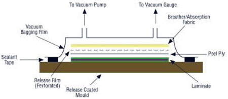
This process is basically an extension of the wet lay-up process where pressure is applied to the laminate once laid-up in order to improve its consolidation. This is achieved by sealing a plastic film over the wet laid-up laminate and onto the tool. The air under the bag is extracted by a vacuum pump and thus up to one atmosphere of pressure can be applied to the laminate to consolidate it.
VACUUM ASSISTED RESIN TRANSFER MOLDING:
VARTM is a single sided molding process where the dry preform (reinforcement or coring materials) is placed into the mold, a cover (or a vacuum bag) is placed over the top to form a vacuum-tight seal. A distribution medium (a mesh) is used and laid on top of the top release fabric to help maintain an even distribution of resin and facilitate the flow of resin through the thickness of the panel. The low viscosity resin typically enters the preform through resin distribution and vacuum distribution lines with the aid of vacuum. In VARTM process, the flow of resin occurs in plane as well as in the transverse directions to the preform. The permeability of the preform, fiber architecture and fabric crimp have an influence on the wetting of the fabric.
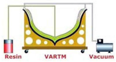
RTM TECHNOLOGY BENEFITS:
Considerably lower mold costs for mold are possible;
Smooth surface on both sides;
Possibility for gelcoat on both sides;
Tolerance stable workpieces;
Environmentally sound production due to closed mold
Dimension: From small to large workpieces
VARTM TECHNOLOGY BENEFITS:
Applicable to larger, less complex and lower volume part production of composite parts;
Simple and low cost tooling;
Onsite manufacturing and reparing are practical ;
High fiber volume panel achievable;
MATERIALS OPTIONS:
Resins: Any, e.g. epoxy, polyester, vinylester, phenolic.
Fibers: Any. woven or stitched into a fabric form.
Cores: Not honeycombs
Materials Options: (VARTM)
Resins: Any resin with low viscosity, e.g. epoxy, polyester, vinylester,
Fibers: Any. woven or stitched into a fabric form.
Cores: Not honeycombs
TYPICAL APPLICATIONS:
Complex aircraft and automotive components, train seats
TYPICAL APPLICATIONS:
VARTM applications including marine, ground transportation and infrastructure parts
SANDWICH CONSTRUCTION:
A typical sandwich construction consists of two strong and relatively thin outer sheets or faces separated by but adhered to a layer of a less-dense and low-cost core material, which has lower strength and lower stiffness. The faces bear most of the in-plane loading and transverse bending stresses. The core separates the faces and resist deformation perpendicular to the face while provides a certain degree of shear rigidity along plane that are perpendicular to the faces. The face materials could be metals (titanium, steel, aluminum alloys), plywood or a fiber-reinforced composite.The core could be foamed plastics, synthetic rubbers, balsa wood, honeycomb, truss,etc.. The sandwich architecture provides exceptional flexural stiffness compared to monocoque structures while reducing weight and cost.
PULTRUSION:
Pultrusion is a manufacturing process for producing continuous lengths of FRP structural shapes. Raw materials include a liquid resin mixture (containing resin, fillers and specialized additives) and reinforcing fibers. The process involves pulling these raw materials (rather than pushing as is the case in extrusion) through a heated steel forming die using a continuous pulling device. The reinforcement materials are in continuous forms such as rolls of fiberglass mat or doffs of fiberglass roving. As the reinforcements are saturated with the resin mixture ("wet-out") in the resin impregnator and pulled through the die, the gelation (or hardening) of the resin is initiated by the heat from the die and a rigid, cured profile is formed that corresponds to the shape of the die.
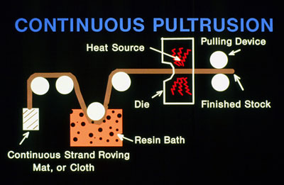
While pultrusion machine design varies with part geometry, the basic pultrusion process concept is described in the following schematic.
While pultrusion machine design varies with part geometry, the basic pultrusion process concept is described in the following schematic.
Pultrusion is a manufacturing process for producing continuous lengths of FRP structural shapes. Raw materials include a liquid resin mixture (containing resin, fillers and specialized additives) and reinforcing fibers. The process involves pulling these raw materials (rather than pushing as is the case in extrusion) through a heated steel forming die using a continuous pulling device. The reinforcement materials are in continuous forms such as rolls of fiberglass mat or doffs of fiberglass roving. As the reinforcements are saturated with the resin mixture ("wet-out") in the resin impregnator and pulled through the die, the gelation (or hardening) of the resin is initiated by the heat from the die and a rigid, cured profile is formed that corresponds to the shape of the die.
While pultrusion machine design varies with part geometry, the basic pultrusion process concept is described in the following schematic.
The creels position the reinforcements for subsequent feeding into the guides. The reinforcement must be located properly within the composite and controlled by the reinforcement guides.
The resin impregnator saturates (wets out) the reinforcement with a solution containing the resin, fillers, pigment, and catalyst plus any other additives required. The interior of the resin impregnator is carefully designed to optimize the "wet-out" (complete saturation) of the reinforcements.
On exiting the resin impregnator, the reinforcements are organized and positioned for the eventual placement within the cross section form by the preformer. The preformer is an array of tooling which squeezes away excess resin as the product is moving forward and gently shapes the materials prior to entering the die. In the die the thermosetting reaction is heat activated (energy is primarily supplied electrically) and the composite is cured (hardened).
On exiting the die, the cured profile is pulled to the saw for cutting to length. It is necessary to cool the hot part before it is gripped by the pull block (made of durable urethane foam) to prevent cracking and/or deformation by the pull blocks. Two distinct pulling systems are used: a caterpillar counter-rotating type and a hand-over-hand reciprocating type.
In certain applications an RF (radio frequency wave generator) unit is used to preheat the composite before entering the die. When in use, the RF heater is positioned between the resin impregnator and the preformer. RF is generally only used with an all roving part
HIGH STRENGTH
Stronger than structural steel on a pound-for-pound basis. Has been used to form the superstructures of multistory buildings, walkways, sub-floors and platforms.
LIGHTWEIGHT
Pultrusions are 20-25% the weight of steel and 70% the weight of aluminum. Pultruded products are easily transported, handled and lifted into place. Total structures can often be preassembled and shipped to the job site ready for installation.
CORROSION/ROT RESISTANT
Pultruded products will not rot and are impervious to a broad range of corrosive elements. This feature makes pultrusions a natural selection for indoor or outdoor structures in pulp and paper mills, chemical plants, water and sewage treatment plants, structures near salt water and other corrosive environments.
NON-CONDUCTIVE
Glass reinforced pultrusions have low thermal conductivity and are electrically non-conductive.
ELECTRO-MAGNETIC TRANSPARENCY
Pultruded products are transparent to radio waves, microwaves and other electromagnetic frequencies.
DIMENSIONAL STABILITY
The coefficient of thermal expansion of pultruded products is slightly less than steel and significantly less than aluminum.
PARTS CONSOLIDATION
Custom designed pultrusions allow multiple discrete parts to be designed and fabricated into a single part thus reducing the number of fabricated parts and the need to join these parts together.
LOW TEMPERATURE CAPABILITIES
Glass fiber reinforced pultrusions exhibit excellent mechanical properties at very low temperatures, even -70∞F. Tensile strength and impact strengths are greater at -70∞F than at +80∞F.
AESTHETICS:
Pultruded profiles are pigmented throughout the thickness of the part and can be made to virtually any desired custom color. Special surfacing veils are also available to create special surface appearances such as wood grain, marble, granite, etc.
EXTRUSION:
A thermoplastic process whereby pellets, granules, or powder are melted and forced through a die under pressure to form a given, continuous shape. Typical shapes extruded are flat films and sheets, filaments and fibers, strands for pelletizing, and webs for coating and laminating. Also used for forming composite preformed materials from mixtures of a matrix powder and short fibers suitable for MMCs. Widely used for continuous production of film, sheet, tube, and other profiles; also used in conjunction with blow molding. Thermoplastic or thermoset molding compound is fed from a hopper to a screw and barrel where it is heated to plasticity then forwarded, usually via a rotating screw, through a nozzle possessing the desired cross section. Production lines require input and takeoff equipment that can be complex.
Low tool cost, numerous complex profile shapes possible, very rapid production rates, can apply coatings or jacketing to core materials such as wire).
Familiar products manufactured by extrusion include: pipes, ingot, guttering, window sills and insulation on wires.
RESIN TRANSFER MOLDING:
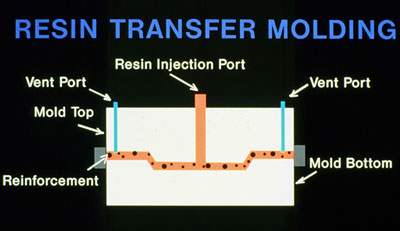
Resin Transfer Molding (RTM) is a particular useful manufacturing process processes that use liquid resin to impregnate the stationary fibrous preform. During the RTM Process, the preform is placed into the mold cavity, the mold is closed and the resin is injected into the cavity under pressure. The mold with the preform is often put under vacuum so that the vacuum removes all the entrapped air in the preform and speeds up the RTM process. Once the liquid resin fills the mold cavity, it cures, during which the resin hardens due to the formation of polymeric network forming the matrix of the composite, allowing the part to be de-molded. Typically thermoset polymers of Epoxy, Vinyl Ester, Methyl Methacrylate, Polyester or Phenolic are used with fiberglass, carbon fiber Arimid and synthetic fibers reinforcements either individually or in combination with each other. This technique is well known and has been traditionally applied to moderately large parts in various application. It allows one to obtain even very complex neat-shape parts with good surface finish, in many cases at reasonable production rates.The fiber architecture, permeability of the preform and the fabric crimps, resin viscosity, temperature of operation, have an influence on the wetting of the fabric. Careful process design is needed to obtain a repeatable high quality product.
COMPRESSION MOLDING:
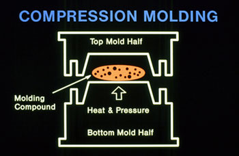
In compression moulding, two matched (usually steel) mould halves are mounted in a (normally hydraulic) press with movement limited to the axis normal to the plane of the mould. This process tends to be associated with a variety of materials, including (but not a limited list):
ï prepreg continuous fibres in epoxy resin
ï prepreg short fibres in polyester resin (sheet moulding compound - SMC)
ï dough moulding compound (SMC)
ï bulk moulding compound (BMC)
ï prepreg short fibre in a thermoplastic matrix (glass mat thermoplastics - GMT)
The moulds may be heated or the composite may be preheated and formed in relatively cool moulds. A limitation on the process is the uniaxial force applied - as a consequence while horizontal surfaces are subject to compression loads as the component surfaces change to vertical there is little or no component of the force acting to consolidate the material in that plane. Further near vertical surfaces may be subjected to wrinkling during mould closure. These issues may be resolved by the use of rubber-block moulding or hydroforming (pressurised liquid contained in a flexible membrane) wholly or partially substituting the male mould half.
AUTOCLAVE CURING:
Autoclaves are used to process both laminated composites and bonded metallic assemblies, for example honeycomb panels. While under vacuum, or vented, heat and pressure can be adjusted to optimize the fiber/resin ratio in composite parts and provide high strength bonds (using high strength film adhesives) in bonded assemblies.
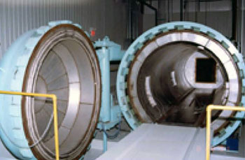
Benefits of the Autoclave Cure
Highest strength to weight ratio
High fiber content laminates
Pressurized curing and reduced voids
Ability to process large parts or a number of small ones
Pressure and heat can be controlled very closely
Strategic fiber placement Flatness
TYPICAL APPLICATIONS
Precision curing parts, aircraft parts, PCB's, Laminates, and thermoset components for the electronics industry.
FIBRE PLACEMENT:
Investigations are also being carried out with fibre placement, a cost-effective and highly automated manufacturing process that can replace the labour-intensive hand lay-up of composite materials prior to curing in an autoclave. The technology, which combines filament winding with automated tape placement, is best suited to the production of medium to large-sized parts with moderate to high degrees of curvature and a high level of structural integration.
New developments as shown below, illustrate how carbon roving and other fibre material can be CNC stitched in an pre-designed pattern to optimize material use and strength properties for use in medical or other highly specialized applications.
